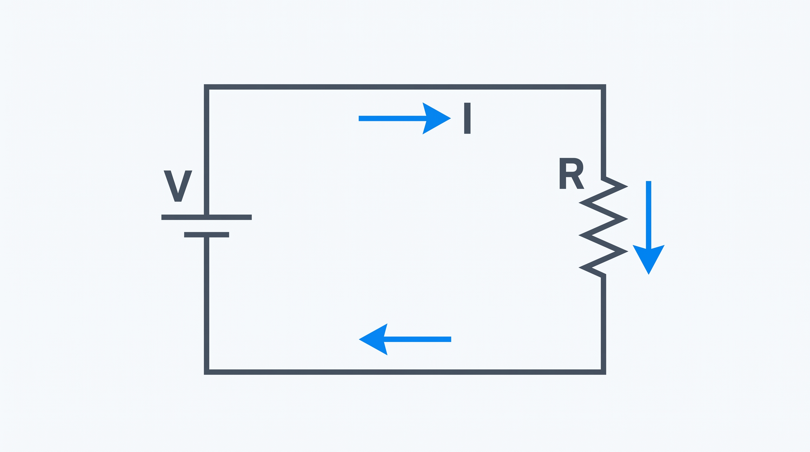
To understand electrical engineering, it is important to understand three basic electrical quantities: voltage, current and resistance. These quantities appear in almost every electrical circuit and are closely related.
Their relationship is described by Ohm's Law, which is one of the fundamental relationships used for electrical circuit analysis.
What Is Voltage?
Voltage is the electrical potential difference between two points in a circuit. A voltage difference provides the potential that can drive electric charge through a circuit.
Voltage is measured in volts (V).
A useful beginner-level analogy is water pressure. A pressure difference can drive water through a pipe. Similarly, an electrical potential difference can drive charge through an electrical circuit.
Examples of Voltage
Examples of commonly encountered voltage levels include:
- A typical AA battery: approximately 1.5 V
- A common USB supply: approximately 5 V
- A typical automotive electrical system: approximately 12 V
- Residential and commercial AC systems use higher voltages depending on the electrical system and country.
What Is Electric Current?
Electric current is the rate at which electric charge flows through a conductor or electrical circuit.
Current is measured in amperes (A), commonly called amps.
In the water analogy, current can be compared with the amount of water flowing through a pipe per unit of time.
Conventional Current
In conventional circuit analysis, current direction is defined from higher electric potential toward lower potential through the external circuit.
In metallic conductors, electrons move in the opposite direction to conventional current.
This distinction is important when analysing electrical circuits and electronic systems.
What Is Electrical Resistance?
Electrical resistance describes the opposition to electric current in a material or component.
Resistance is measured in ohms (Ω).
Using the water analogy, resistance can be compared with a restriction that makes fluid flow more difficult.
Factors Affecting Resistance
For a uniform conductor, resistance depends mainly on the material, length, cross-sectional area and temperature.
The basic relationship is:
- R = Resistance (Ω)
- ρ = Resistivity (Ω·m)
- L = Conductor length (m)
- A = Cross-sectional area (m²)
How Voltage, Current and Resistance Are Related
Voltage, current and resistance are related through Ohm's Law.
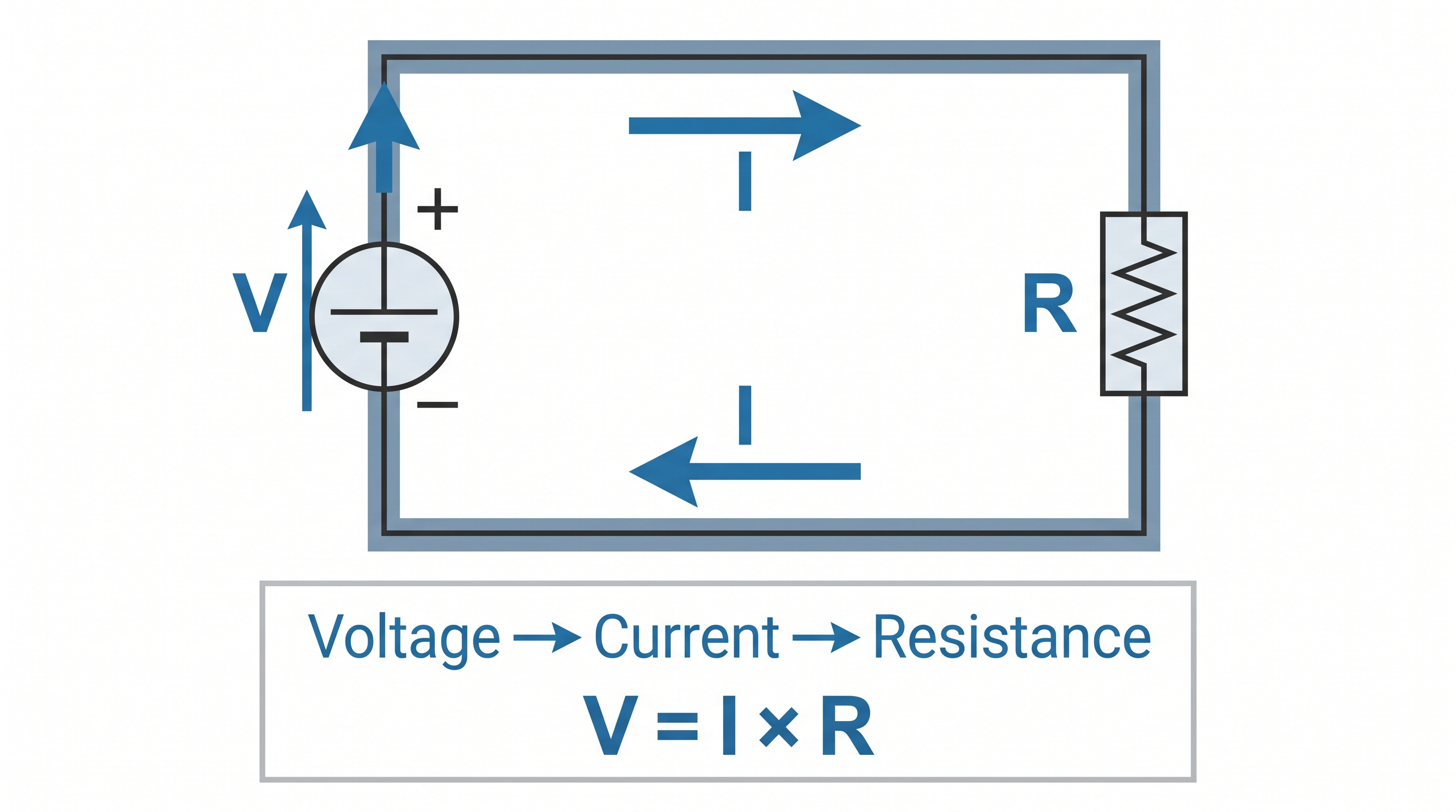
For an ohmic component under appropriate conditions, increasing the applied voltage while resistance remains constant increases the current.
Similarly, increasing resistance while the voltage remains constant reduces the current.
The Three Basic Ohm's Law Equations
The basic equation can be rearranged to calculate any one of the three quantities when the other two are known.
Calculate Voltage
Calculate Current
Calculate Resistance
Practical Example
Consider a simple DC circuit supplied by a 12 V source and connected to a 6 Ω resistor.
Given
- Voltage = 12 V
- Resistance = 6 Ω
Calculate the current.
Using Ohm's Law:
Therefore, the current through the resistor is 2 A, assuming the stated circuit conditions and an appropriate ohmic model.
Voltage, Current and Resistance: Water Analogy
A water-system analogy can help beginners develop an intuitive understanding of voltage, current and resistance.
| Electrical Quantity | Water Analogy | Unit |
|---|---|---|
| Voltage | Pressure difference | Volt (V) |
| Current | Water flow rate | Ampere (A) |
| Resistance | Restriction to flow | Ohm (Ω) |
The analogy is useful for developing intuition, but real electrical systems involve electromagnetic behaviour and circuit effects that are more complex than a simple pipe-and-water model.
Voltage, Current and Resistance in a Series Circuit
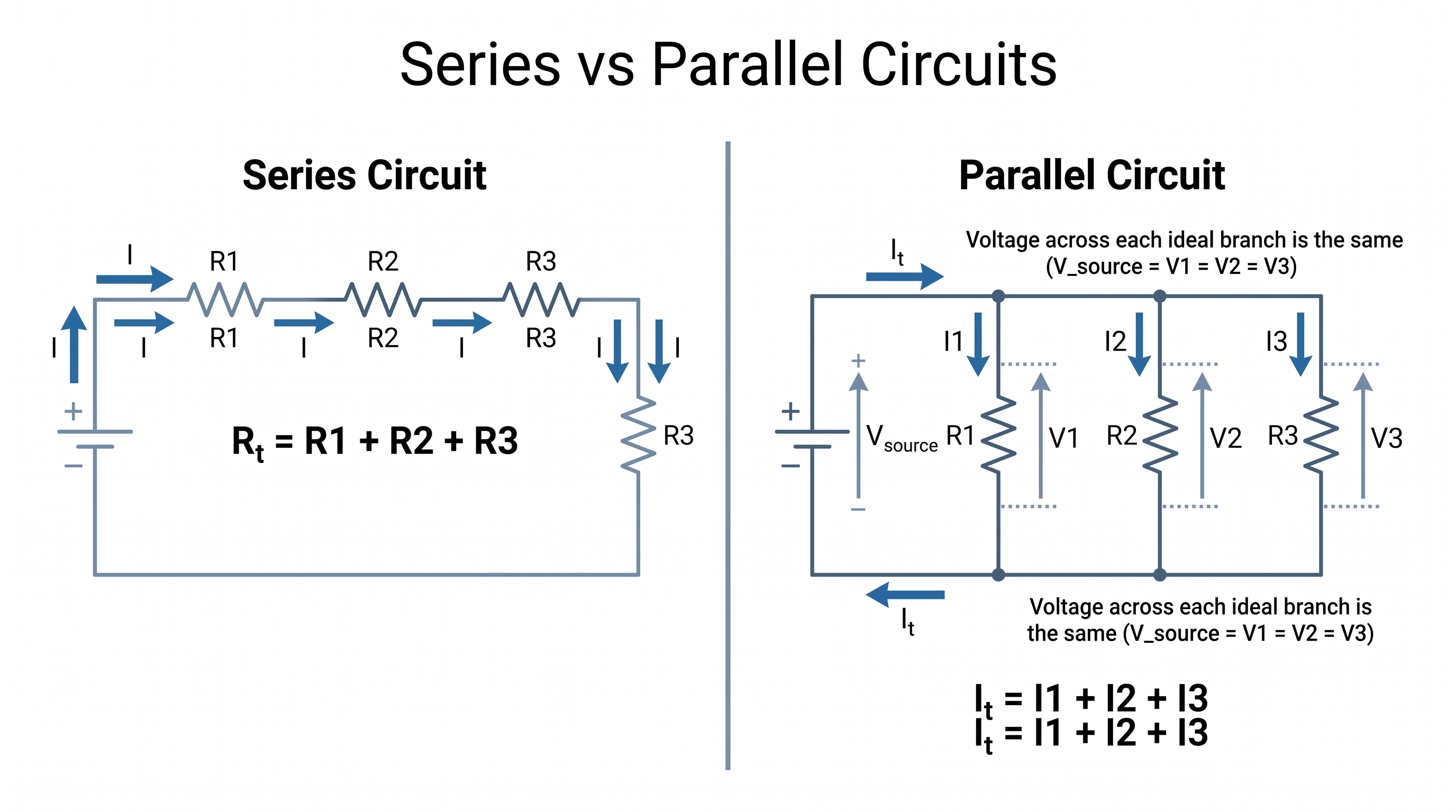
In a basic series circuit, the same current flows through each series component.
For resistors connected in series, the total resistance is:
The source voltage is distributed among the components according to their individual voltage drops.
Voltage, Current and Resistance in a Parallel Circuit
In an ideal parallel circuit, each branch is connected across the same two supply nodes. Therefore, the voltage across each branch is the same.
The total current is the sum of the branch currents:
For resistors connected in parallel:
Relationship With Electrical Power
Voltage and current are also related to electrical power.
Combining the power equation with Ohm's Law gives:
These relationships are useful when analysing resistive loads, circuit components and electrical power consumption.
Practical Electrical Engineering Applications
Understanding voltage, current and resistance is essential in many practical engineering activities.
- Electrical circuit analysis
- Voltage-drop calculations
- Cable sizing
- Fuse and circuit-breaker selection
- Resistor selection
- Battery system analysis
- DC system design
- Solar PV system calculations
- Electrical troubleshooting
- Testing and commissioning
Common Mistakes Beginners Make
Confusing Voltage With Current
Voltage and current are different electrical quantities. Voltage is a potential difference, while current represents the rate of electric charge flow.
Confusing Current With Power
Current is measured in amperes, while electrical power is measured in watts. They are related, but they are not the same physical quantity.
Forgetting Units
Always check units when performing electrical calculations. Voltage should be expressed in volts, current in amperes and resistance in ohms when using the basic Ohm's Law equations directly.
Assuming Every Device Is Ohmic
Not every electrical device has a constant resistance. Components such as diodes and many semiconductor devices have nonlinear voltage-current characteristics.
Frequently Asked Questions
What is voltage?
Voltage is the electrical potential difference between two points in a circuit. It is measured in volts (V).
What is electric current?
Electric current is the rate at which electric charge flows through a conductor or circuit. It is measured in amperes (A).
What is electrical resistance?
Electrical resistance is the opposition offered to the flow of electric current. It is measured in ohms (Ω).
How are voltage, current and resistance related?
They are related by Ohm's Law: V = I × R.
What are the units of voltage, current and resistance?
Voltage is measured in volts (V), current in amperes (A), and resistance in ohms (Ω).
Summary
Voltage, current and resistance are fundamental electrical quantities that form the basis of circuit analysis.
| Quantity | Symbol | Unit | Basic Meaning |
|---|---|---|---|
| Voltage | V | Volt (V) | Electrical potential difference |
| Current | I | Ampere (A) | Rate of electric charge flow |
| Resistance | R | Ohm (Ω) | Opposition to current flow |
Their fundamental relationship can be expressed using Ohm's Law:
Understanding these three quantities provides a foundation for more advanced topics such as electrical power, voltage drop, circuit analysis, cable sizing, equipment calculations and electrical system design.