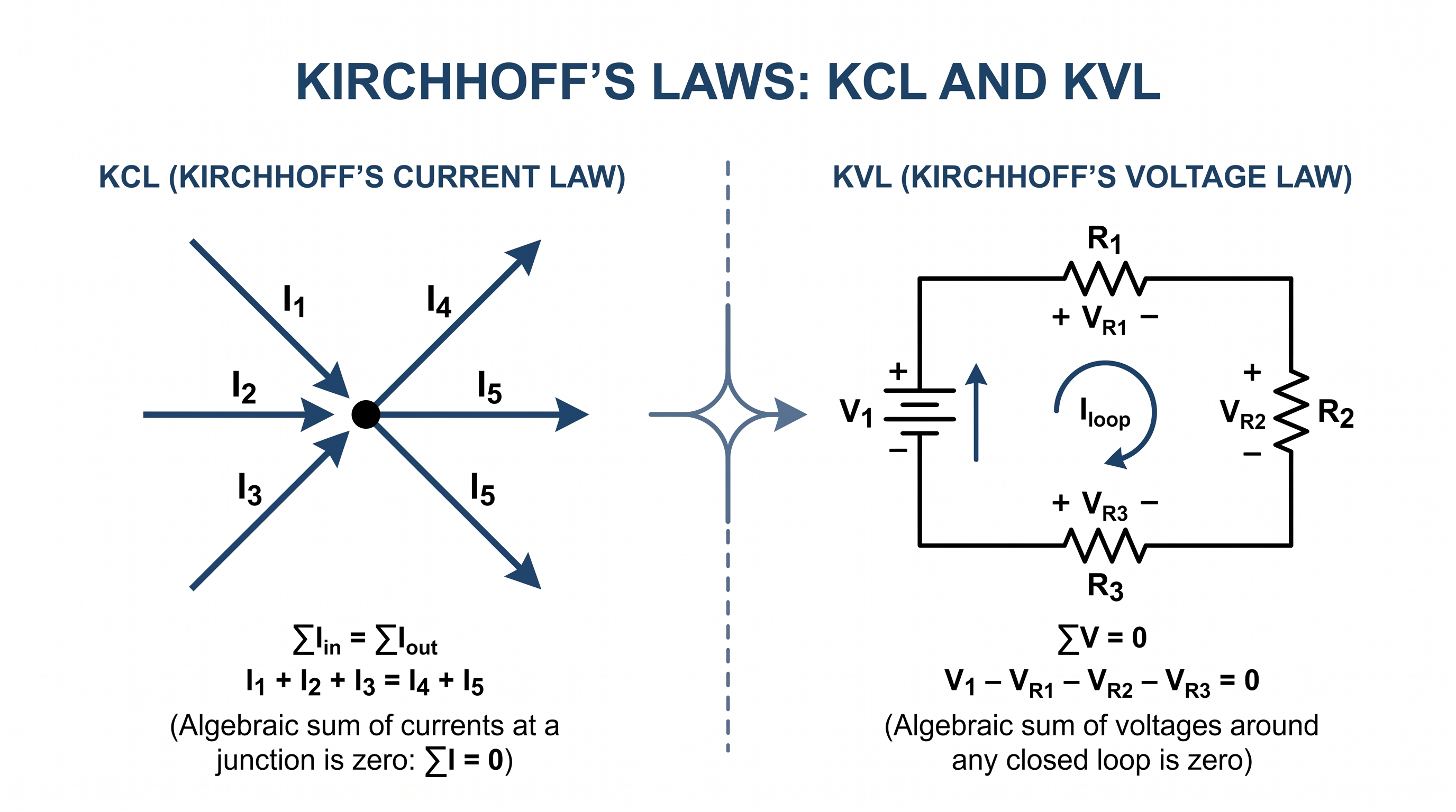
Kirchhoff's Laws are fundamental principles used to analyze electrical circuits. They are especially useful when a circuit contains multiple branches, nodes, voltage sources or loops that cannot be analyzed conveniently using only Ohm's Law.
The two laws are:
- Kirchhoff's Current Law (KCL) — applies to currents at a circuit node or junction.
- Kirchhoff's Voltage Law (KVL) — applies to voltage changes around a closed circuit loop.
KCL is based on the conservation of electric charge, while KVL is based on the conservation of energy. Together with Ohm's Law, they provide a foundation for systematic electrical circuit analysis.
What Are Kirchhoff's Laws?
Kirchhoff's Laws were formulated by German physicist Gustav Kirchhoff and became fundamental tools for electrical circuit analysis.
They are particularly useful for circuits that contain several branches and loops and cannot be reduced easily into simple series and parallel combinations.
Kirchhoff's first law is the junction rule, now commonly called KCL. It relates the currents entering and leaving a node.
Kirchhoff's second law is the loop rule, now commonly called KVL. It relates the voltage changes encountered while travelling around a closed path.
These rules are applications of two fundamental conservation principles:
- KCL: Conservation of electric charge
- KVL: Conservation of energy
Kirchhoff's Current Law (KCL)
Kirchhoff's Current Law (KCL) states that the algebraic sum of currents at a node is zero.
An equivalent and commonly used form is:
KCL follows from the conservation of electric charge. In an ideal lumped circuit model, charge does not continuously accumulate at a node. Therefore, current entering a junction must be balanced by current leaving it.
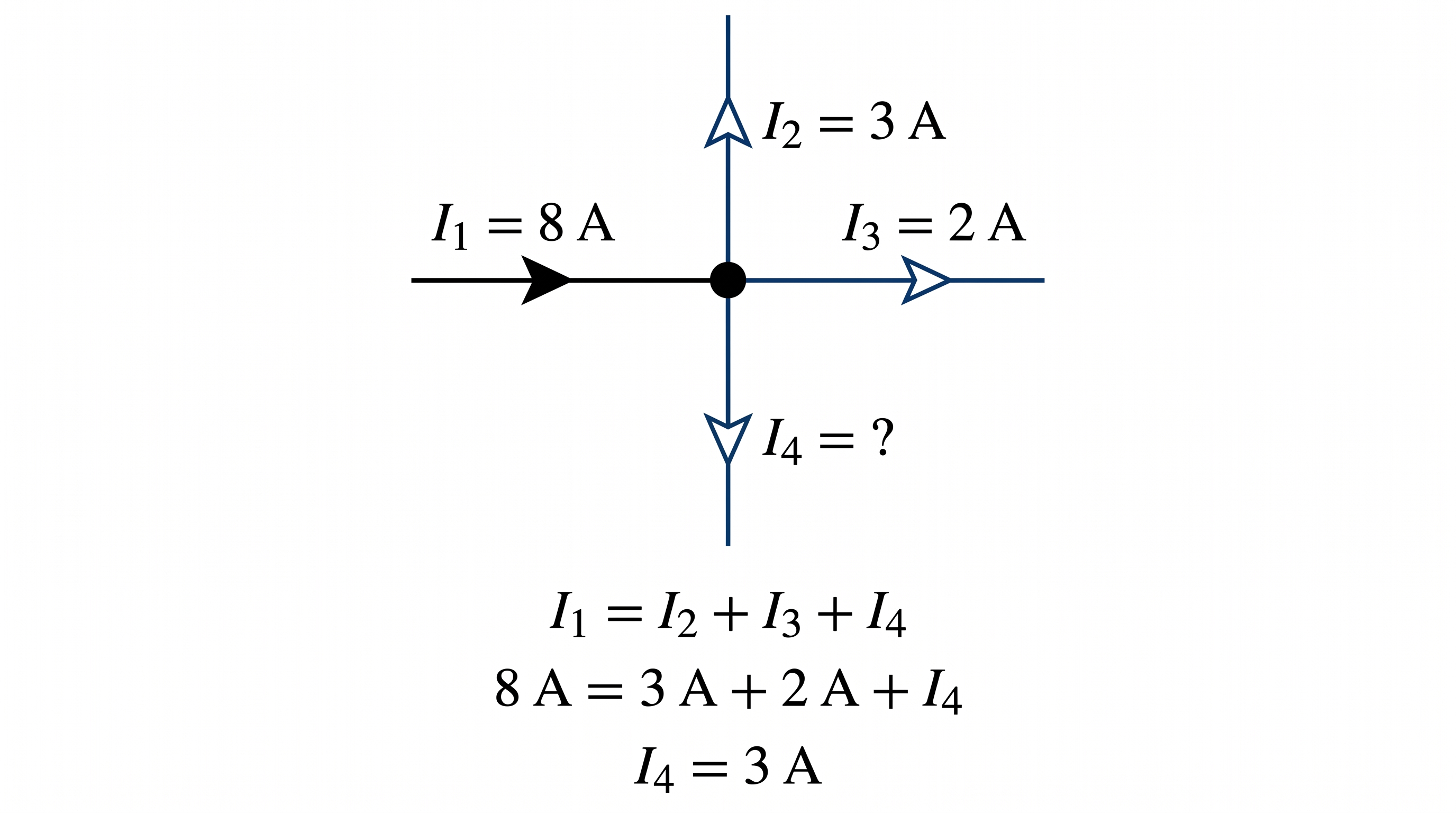
KCL Formula
KCL can be written in two equivalent forms.
Form 1: Incoming and outgoing currents
Form 2: Algebraic sum
For the algebraic form, a sign convention must be selected. For example, currents entering a node may be considered positive and currents leaving the node negative.
If a node has two currents entering and two currents leaving, an equation may be written as:
Therefore:
KCL Worked Example
Consider a circuit node where two currents enter the node and two currents leave it.
Given
- I1 = 8 A entering
- I2 = 5 A entering
- I3 = 7 A leaving
- I4 = unknown leaving current
Apply KCL:
Substitute the known values:
Therefore:
I4 = 6 A
Therefore: I4 = 6 A.
Check:
13 = 13
The KCL equation is satisfied.
Why Does KCL Work?
KCL is an application of the conservation of electric charge. Electric current represents the rate at which electric charge moves through a circuit.
Therefore, if charge flows into a circuit node, an equal amount of charge must leave the node in the corresponding steady-state circuit model.
This gives the fundamental KCL relationship:
KCL is therefore not simply an empirical circuit formula. It follows from a fundamental conservation principle.
Kirchhoff's Voltage Law (KVL)
Kirchhoff's Voltage Law (KVL) states that the algebraic sum of all voltage changes around any closed circuit loop is zero.
Another useful form is:
KVL is based on the conservation of energy. When a charge completes a closed path through a circuit, the net energy change associated with the circuit elements must balance.
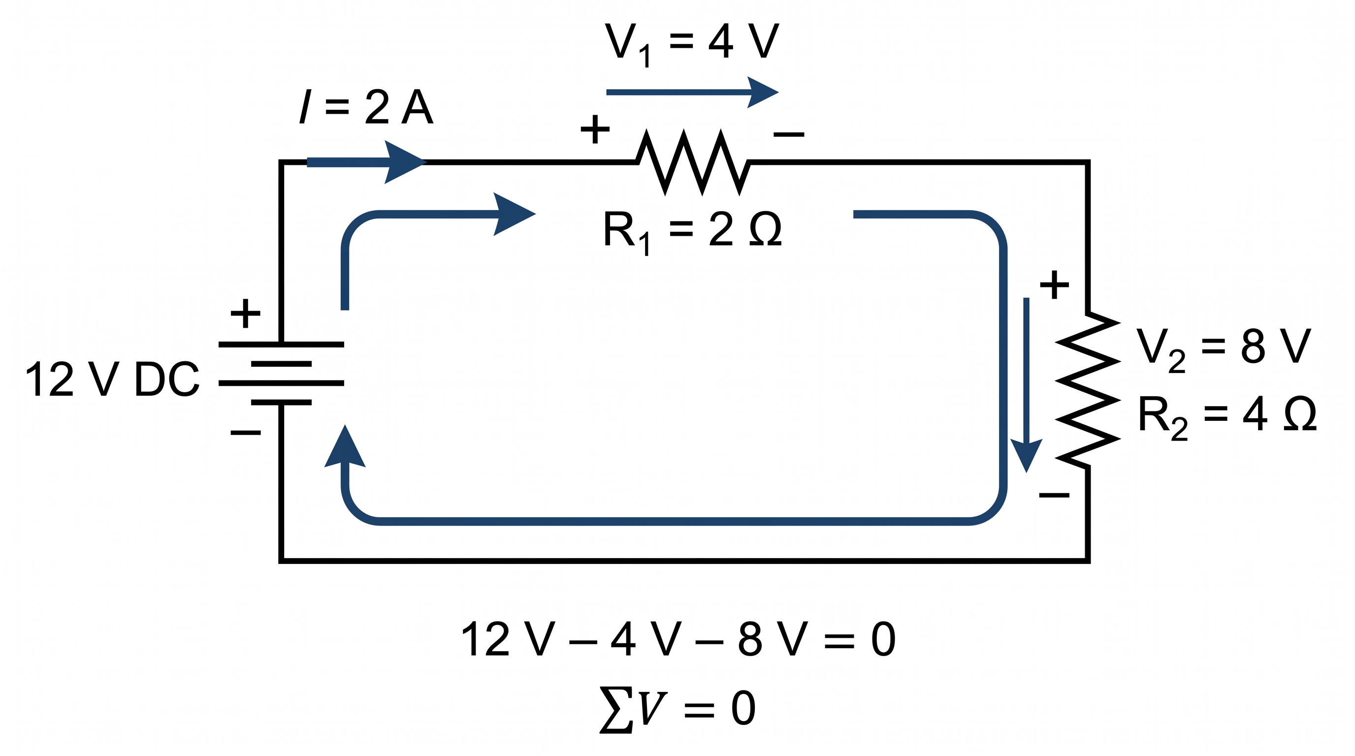
KVL Formula
For a closed circuit loop:
For a simple circuit with one voltage source and several resistive voltage drops:
Therefore:
This means that the voltage supplied by the source equals the total voltage drop around the loop.
KVL Sign Convention
Correct sign convention is essential when applying KVL.
First choose a direction in which to travel around the loop. You may choose clockwise or counterclockwise.
The important requirement is to remain consistent throughout the equation.
Crossing a Voltage Source
When travelling from the negative terminal of an ideal voltage source to its positive terminal, the voltage change is normally treated as a positive voltage rise:
When travelling from the positive terminal to the negative terminal, the voltage change is:
Crossing a Resistor
Using the passive sign convention, travelling through a resistor in the direction of the assumed current produces a voltage drop:
Travelling through the resistor opposite to the assumed current direction produces:
KVL Worked Example
Consider a simple DC circuit with a 24 V source and two resistors. The first resistor has a voltage drop of 9 V and the second resistor has an unknown voltage drop.
Given
- Source voltage = 24 V
- Voltage drop across R1 = 9 V
- Voltage drop across R2 = unknown
Apply KVL:
Therefore:
VR2 = 15 V
Therefore, the voltage drop across the second resistor is: 15 V.
Check:
The KVL equation is satisfied.
KCL vs KVL
KCL and KVL are complementary laws, but they are applied to different parts of a circuit.
| Feature | KCL | KVL |
|---|---|---|
| Full name | Kirchhoff's Current Law | Kirchhoff's Voltage Law |
| Also called | Junction rule | Loop rule |
| Main quantity | Current | Voltage |
| Applied to | Nodes or junctions | Closed loops |
| Conservation principle | Electric charge | Energy |
| Basic equation | ΣI = 0 | ΣV = 0 |
A simple way to remember the difference is:
Ohm's Law and Kirchhoff's Laws
Kirchhoff's Laws do not replace Ohm's Law. In practical circuit analysis, the three principles are often used together.
Ohm's Law provides the relationship between voltage, current and resistance:
KCL provides the relationship between branch currents at a node:
KVL provides the relationship between voltage changes around a closed loop:
By combining these equations, unknown currents and voltages can be determined in circuits containing multiple branches and loops.
Worked Example Using Ohm's Law and KVL
Consider a simple 12 V DC circuit with two series resistors:
Given
- Source voltage = 12 V
- R1 = 2 Ω
- R2 = 4 Ω
Since there is only one current path, the same current flows through both resistors.
Apply KVL:
Using Ohm's Law:
V2 = IR2
Substitute these relationships into the KVL equation:
Therefore:
6I = 12
I = 2 A
Therefore, the circuit current is: 2 A.
Now calculate the voltage drop across each resistor.
V2 = 2 × 4 = 8 V
Check the result using KVL:
Therefore, both Ohm's Law and KVL are satisfied.
Using KCL and KVL Together
The real power of Kirchhoff's Laws becomes apparent when a circuit contains multiple branches and loops.
For example, if a current enters a node and divides into two branches, KCL can establish the relationship:
KVL can then be applied to separate loops to establish voltage relationships involving the branch currents.
Ohm's Law can relate the voltage and current of individual resistors:
The resulting equations can then be solved simultaneously.
This approach forms the basis of systematic methods such as nodal analysis and mesh analysis.
How to Solve a Circuit Using Kirchhoff's Laws
A practical procedure for solving a circuit using Kirchhoff's Laws is:
- Identify all circuit components.
- Identify the important nodes and branches.
- Assign a reference direction to each unknown current.
- Apply KCL at the required nodes.
- Identify the independent closed loops.
- Choose a direction for travelling around each loop.
- Apply KVL to each required loop.
- Use Ohm's Law to express voltage drops across resistors where necessary.
- Solve the resulting simultaneous equations.
- Check the calculated currents and voltages against KCL and KVL.
Number of Equations Required
When applying Kirchhoff's Laws to a circuit, the number of independent equations must be sufficient to determine the unknown quantities.
For example, if a circuit contains three independent unknown branch currents, three independent equations may be required.
Some KCL equations may be dependent on one another, so writing every possible node equation does not necessarily produce additional independent information.
Likewise, not every possible loop equation needs to be written. A suitable set of independent equations is sufficient to solve the circuit.
What Does a Negative Current Mean?
Suppose the assumed current direction is clockwise, but after solving the equations the result is:
This does not necessarily mean that the calculation is wrong.
It means that the actual current is:
This is one of the advantages of using algebraic circuit analysis: the equations determine the direction as well as the magnitude.
Common Mistakes When Applying KCL and KVL
Beginners often make mistakes when assigning current directions and voltage signs.
1. Confusing Nodes and Loops
KCL is applied at circuit nodes, while KVL is applied around closed loops. A junction is a node where multiple branches meet.
2. Changing the Assumed Current Direction
Once a current direction has been assigned, keep that reference direction throughout the calculation.
3. Ignoring Voltage Polarity
The polarity of voltage sources and resistor voltage drops must be considered when writing KVL equations.
4. Mixing Sign Conventions
Either sign convention can be used, but the same convention must be maintained consistently.
5. Treating a Negative Result as an Error
A negative current or voltage often indicates that the actual direction or polarity is opposite to the assumed reference.
6. Writing Redundant Equations
Not every possible node or loop equation is independent. Use a sufficient set of independent equations.
Applications of Kirchhoff's Laws
Kirchhoff's Laws are used throughout electrical and electronic engineering.
- DC circuit analysis
- AC circuit analysis
- Resistor networks
- Electronic circuits
- Power supply circuits
- Control circuits
- Instrumentation circuits
- Electrical distribution systems
- Electrical machine circuits
- Power-system circuit analysis
- Network analysis
The same fundamental relationships can also be extended to AC circuits, where voltage and current may be represented using phasors and impedances.
Why Kirchhoff's Laws Are Important in Electrical Engineering
Electrical engineering systems often contain circuits that are too complex to analyze by simply adding series and parallel resistances.
Kirchhoff's Laws provide a general framework for establishing the relationships between circuit currents and voltages.
They are therefore an important transition from basic electrical quantities and Ohm's Law to more advanced circuit-analysis techniques.
A typical learning sequence is:
This progression provides a logical foundation for later study of AC circuits, three-phase systems, electrical machines and power systems.
Kirchhoff's Laws Quick Reference
| Principle | Formula | Application |
|---|---|---|
| KCL | ΣI = 0 | Node or junction |
| KCL alternative | ΣIin = ΣIout | Current balance |
| KVL | ΣV = 0 | Closed loop |
| KVL alternative | ΣVrise = ΣVdrop | Voltage balance |
| Ohm's Law | V = IR | Individual circuit element |
Summary
Kirchhoff's Laws are fundamental tools for analyzing electrical circuits.
Kirchhoff's Current Law (KCL) states that the total current entering a node equals the total current leaving the node:
KCL is based on the conservation of electric charge.
Kirchhoff's Voltage Law (KVL) states that the algebraic sum of all voltage changes around a closed loop is zero:
KVL is based on the conservation of energy.
Together with Ohm's Law:
these principles provide the foundation for analyzing many electrical circuits.
Frequently Asked Questions
What is Kirchhoff's Current Law (KCL)?
Kirchhoff's Current Law states that the algebraic sum of currents at a circuit node is zero. Equivalently, the total current entering a node equals the total current leaving the node.
What is Kirchhoff's Voltage Law (KVL)?
Kirchhoff's Voltage Law states that the algebraic sum of all voltage changes around any closed circuit loop is zero.
What is the difference between KCL and KVL?
KCL deals with current at circuit nodes and is based on conservation of charge. KVL deals with voltage around closed loops and is based on conservation of energy.
Can Kirchhoff's Laws be used with Ohm's Law?
Yes. Kirchhoff's Laws and Ohm's Law are commonly used together to determine unknown currents and voltages in electrical circuits.
What happens if a calculated Kirchhoff current is negative?
A negative current normally means that the actual current flows in the direction opposite to the assumed reference direction.
What Comes Next?
Now that KCL and KVL have been introduced, the next step is to apply these principles systematically to DC circuit analysis.
The next topic will build on Ohm's Law, KCL and KVL to determine unknown currents and voltages in practical DC circuits.