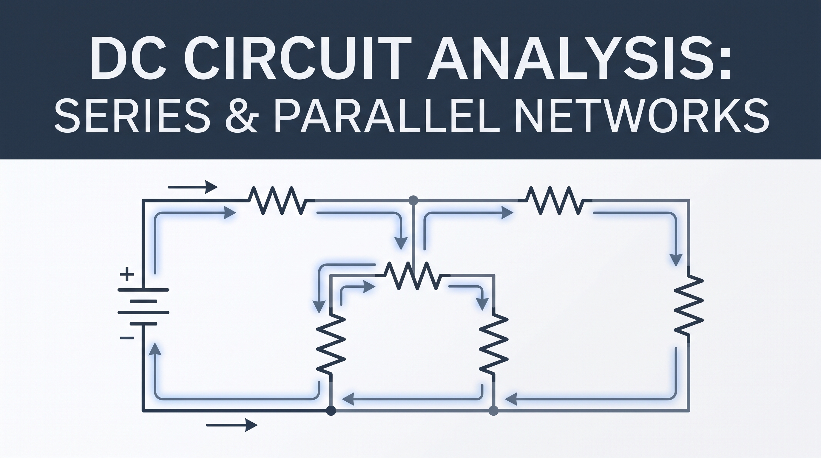
DC circuit analysis is the process of calculating unknown voltages, currents, and power levels within a direct current electrical network. Whether designing microelectronic sensors, industrial control loops, or photovoltaic DC combiners, understanding how resistors and loads behave in series and parallel configuration is essential.
All DC circuit reduction relies on combining basic component arrangements:
- Series Connections — components connected end-to-end along a single continuous path.
- Parallel Connections — components connected across common voltage nodes to provide multiple current paths.
- Series-Parallel Combinations — complex networks combining both series and parallel subnetworks.
By applying Ohm's Law along with Kirchhoff's Current Law (KCL) and Kirchhoff's Voltage Law (KVL), complex DC networks can be systematically reduced into simple, manageable equivalent circuits.
What Is DC Circuit Analysis?
Direct Current (DC) flows in a constant direction over time, driven by steady voltage sources such as batteries, DC power supplies, or solar PV strings. DC circuit analysis evaluates these networks under steady-state conditions where voltages and currents are constant.
Analyzing a circuit means determining the complete state of the network, including:
- Total current supplied by the voltage or current sources
- Equivalent resistance seen by the power source
- Individual branch currents across every circuit leg
- Voltage drops across each individual component or resistor
- Power dissipated by loads or delivered by power sources
Before tackling complex network theorems like Thevenin's or Norton's theorems, mastering basic series and parallel reduction techniques is mandatory.
Series Circuits Explained
A series circuit exists when circuit elements are joined sequentially, forming a single closed path for electrical charge to flow.
Because there is only one continuous loop, charge cannot accumulate or branch off. Consequently, the current passing through every series element is exactly equal.
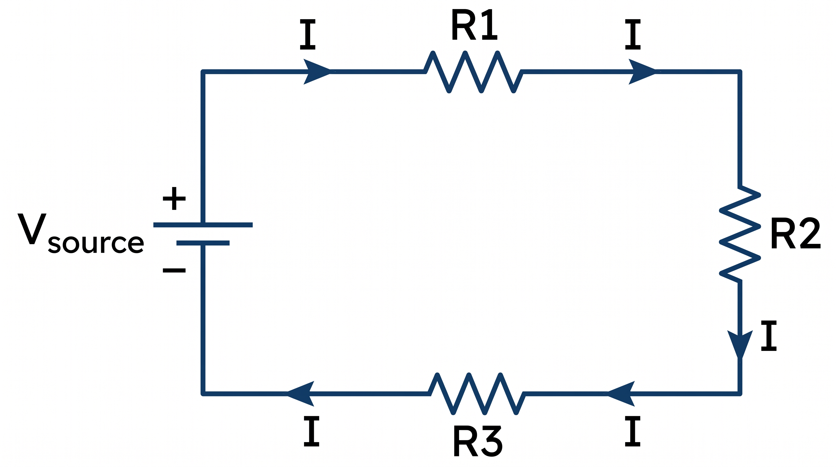
Key properties of series circuits include:
- Current is constant: The same current I flows through all components.
- Voltages add up: The total source voltage equals the sum of individual voltage drops across each component.
- Resistance increases: Adding more resistors in series increases the overall opposition to current flow.
- Single point of failure: If one component opens (burns out), current stops flowing through the entire loop.
Series Circuit Formulas
The fundamental governing equations for a series circuit containing N resistors are:
1. Current Relationship
2. Equivalent Resistance
3. Voltage Drop Summation (KVL)
The Voltage Divider Rule (VDR)
In a series circuit, source voltage divides across resistors in direct proportion to their resistance values. The Voltage Divider Rule (VDR) allows you to calculate the voltage across any specific resistor without calculating total current first.
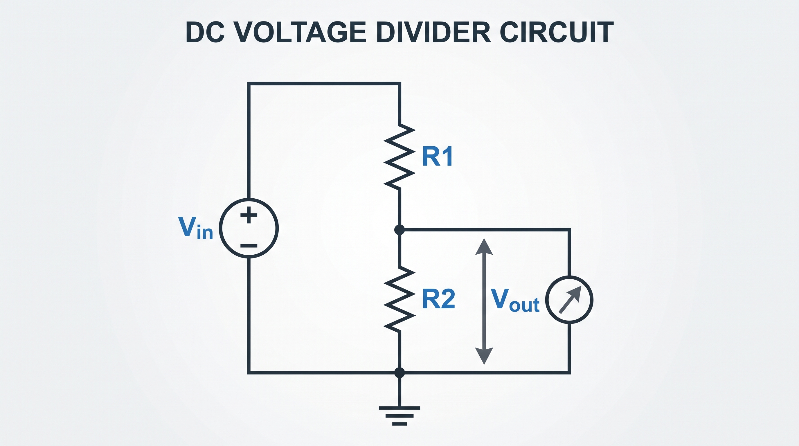
For a two-resistor series circuit, the voltage drop V1 across R1 is:
Series Circuit Worked Example
Consider a 24 V DC power source connected in series with three resistors: R1 = 10 Ω, R2 = 20 Ω, and R3 = 30 Ω.
Given
- VS = 24 V DC
- R1 = 10 Ω
- R2 = 20 Ω
- R3 = 30 Ω
Step 1: Calculate total equivalent resistance (Req)
Req = 10 + 20 + 30 = 60 Ω
Step 2: Calculate total circuit current (IT)
IT = 24 / 60 = 0.4 A (400 mA)
Step 3: Calculate individual voltage drops using Ohm's Law or VDR
V2 = IT × R2 = 0.4 × 20 = 8 V
V3 = IT × R3 = 0.4 × 30 = 12 V
Step 4: Verify with Kirchhoff's Voltage Law
24 = 4 + 8 + 12 = 24 V (Verified)
Parallel Circuits Explained
A parallel circuit occurs when components are connected across the same two electrical nodes, providing multiple independent paths for current flow.
Because all branches share identical node terminals, the voltage across every parallel branch is identical. Total current entering the parallel node splits among branches in inverse proportion to branch resistance.
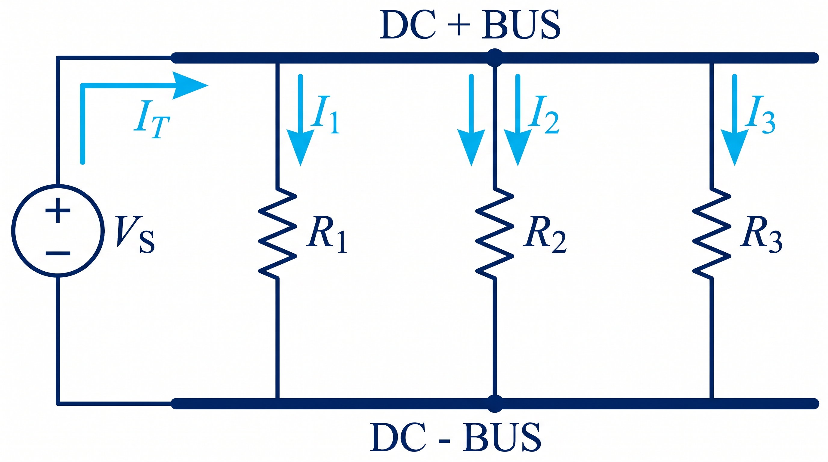
Key properties of parallel circuits include:
- Voltage is constant: The full supply voltage appears across every branch.
- Currents add up: Total supply current equals the sum of individual branch currents (KCL).
- Resistance decreases: Adding parallel branches provides additional current channels, reducing overall equivalent resistance below that of the smallest branch resistor.
- Independent operation: Opening one parallel branch does not interrupt current flow through other branches (standard for household wiring).
Parallel Circuit Formulas
The fundamental equations governing parallel networks with N branches are:
1. Voltage Relationship
2. Equivalent Resistance General Formula
3. Special Case: Two Resistors in Parallel
When dealing with exactly two parallel resistors, the product-over-sum shortcut is highly convenient:
4. Special Case: N Equal Resistors in Parallel
5. Total Current Summation (KCL)
The Current Divider Rule (CDR)
In parallel networks, current divides inversely proportional to resistance; more current flows through paths of lower resistance.
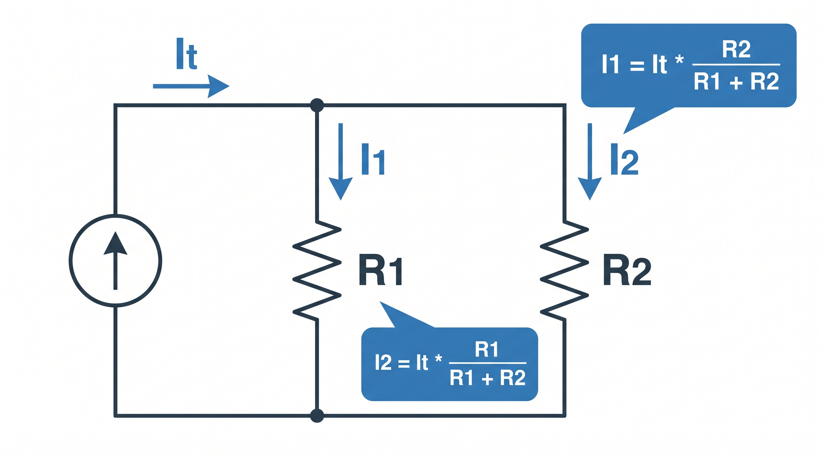
For a two-branch parallel network, the Current Divider Rule (CDR) calculates branch current directly from total entering current IT:
Parallel Circuit Worked Example
A 12 V DC supply is connected across three parallel resistors: R1 = 10 Ω, R2 = 20 Ω, and R3 = 60 Ω.
Given
- VS = 12 V DC
- R1 = 10 Ω
- R2 = 20 Ω
- R3 = 60 Ω
Step 1: Calculate total equivalent resistance (Req)
1 / Req = (6 / 60) + (3 / 60) + (1 / 60) = 10 / 60
Req = 60 / 10 = 6 Ω
Note that Req (6 Ω) is smaller than the smallest single branch resistor (10 Ω).
Step 2: Calculate branch currents using Ohm's Law
I2 = VS / R2 = 12 / 20 = 0.6 A
I3 = VS / R3 = 12 / 60 = 0.2 A
Step 3: Calculate total current (IT) and verify with KCL
IT = I1 + I2 + I3 = 1.2 + 0.6 + 0.2 = 2.0 A (Verified)
Series vs Parallel Circuits Comparison
Understanding structural differences simplifies identifying components in complex schematics:
| Parameter | Series Circuit | Parallel Circuit |
|---|---|---|
| Current Path | Single continuous path | Multiple branching paths |
| Current Behavior | Same through all components | Divides across branches (KCL) |
| Voltage Behavior | Divides across resistors (KVL) | Same across all branches |
| Equivalent Resistance | Req = R1 + R2 + ... | 1/Req = 1/R1 + 1/R2 + ... |
| Effect of Adding Resistor | Increases total resistance | Decreases total resistance |
| Component Open Failure | Stops all current flow | Other branches keep operating |
| Primary Analysis Rule | Voltage Divider Rule (VDR) | Current Divider Rule (CDR) |
Series-Parallel Combination Circuits
Practical engineering schematics rarely consist solely of pure series or pure parallel connections. Instead, they feature series-parallel combinations.
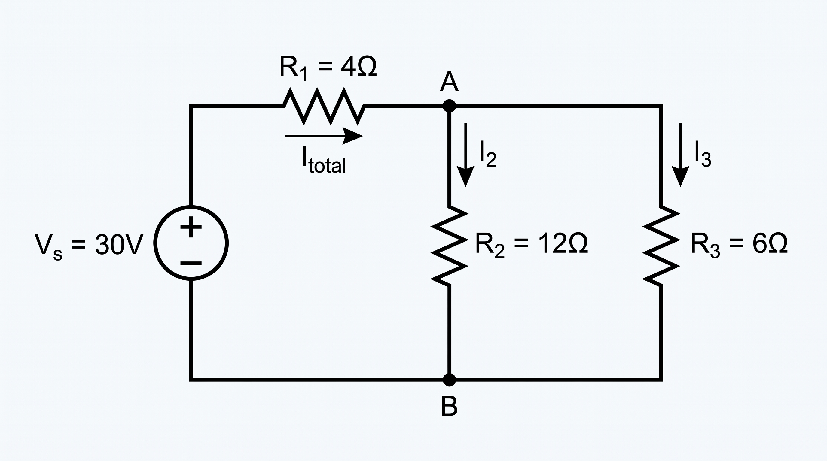
To analyze a combination circuit, apply the Block Reduction Method:
- Identify purest sub-blocks: Look for pairs of resistors clearly connected in pure series or pure parallel without interfering node taps.
- Replace with equivalent resistance: Calculate Req for that sub-block and redraw the schematic replacing the block with a single equivalent resistor.
- Repeat systematically: Continue reducing parallel and series blocks inward until a single global equivalent resistance (Req, total) remains.
- Work backward (Expansion): Calculate total source current, then expand step-by-step outward to find individual node voltages and branch currents using VDR, CDR, and Ohm's Law.
Series-Parallel Combination Worked Example
Analyze the circuit below: A 30 V DC source is connected to resistor R1 = 4 Ω in series with a parallel block consisting of R2 = 12 Ω and R3 = 6 Ω.
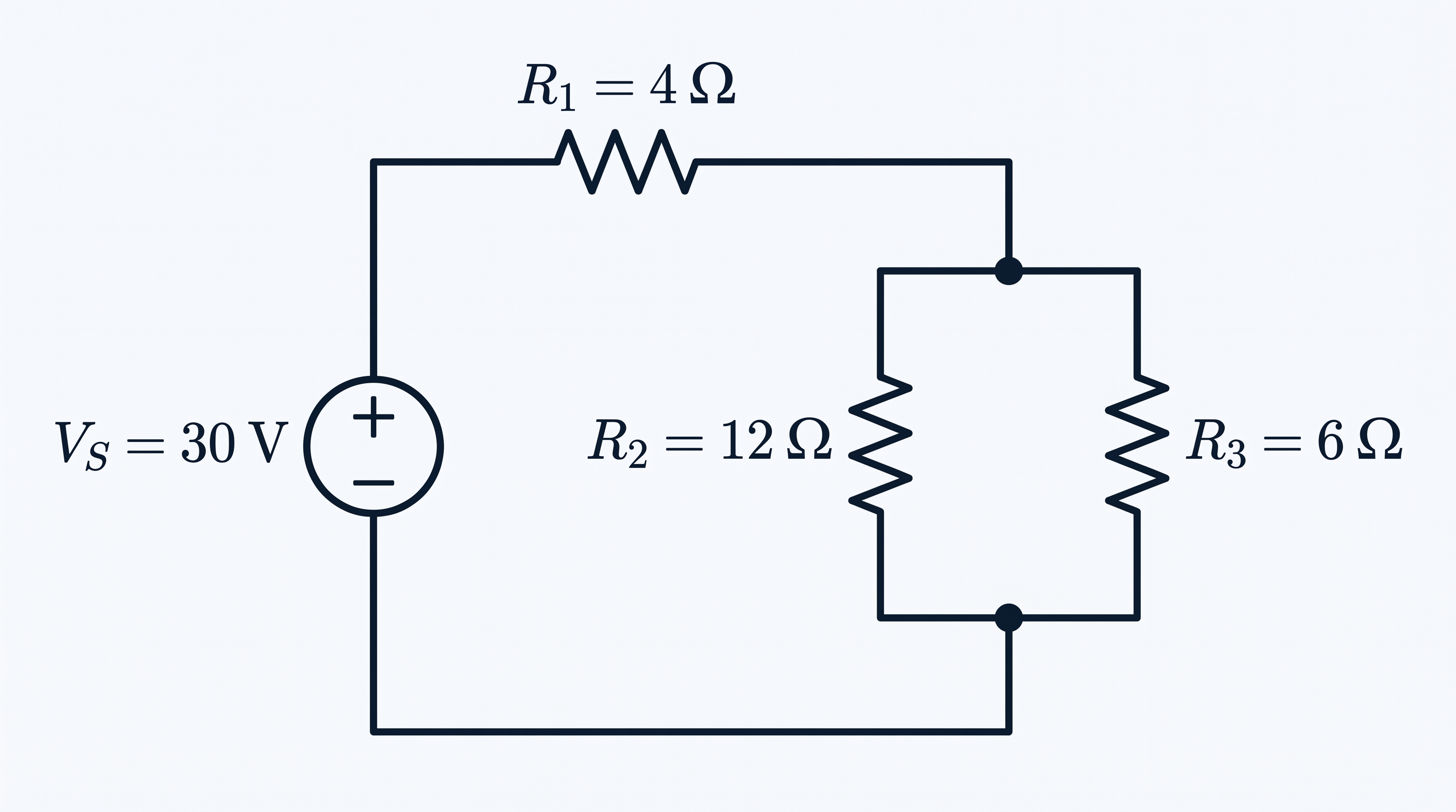
Given
- VS = 30 V DC
- R1 = 4 Ω (in series with parallel pair R2 || R3)
- R2 = 12 Ω
- R3 = 6 Ω
Step 1: Reduce parallel sub-block (R2 || R3)
Rp = (12 × 6) / (12 + 6) = 72 / 18 = 4 Ω
Step 2: Calculate total circuit equivalent resistance (Req)
The circuit now simplifies to R1 in series with Rp:
Req = 4 + 4 = 8 Ω
Step 3: Calculate total supply current (IT)
Step 4: Calculate voltage across R1 and across parallel block Rp
VRp = IT × Rp = 3.75 × 4 = 15 V
Step 5: Calculate individual currents through parallel branches R2 and R3
Using Ohm's Law across the parallel block voltage (15 V):
I3 = VRp / R3 = 15 / 6 = 2.50 A
Alternatively, using Current Divider Rule on parallel pair:
I3 = 3.75 × (12 / 18) = 2.50 A
Verification (KCL at parallel junction node): IT = I2 + I3 → 3.75 = 1.25 + 2.50 = 3.75 A.
Common Mistakes in DC Circuit Analysis
Avoid these standard pitfalls when performing network calculations:
1. Misidentifying Series Components
Assuming two components are in series when a third branch attaches at the junction node. Components are strictly in series ONLY if no intermediate connections extract or inject current.
2. Misapplying the Two-Resistor Parallel Formula
Attempting to use (R1 × R2 × R3) / (R1 + R2 + R3) for three parallel resistors. This is mathematically invalid! Use 1/Req = 1/R1 + 1/R2 + 1/R3.
3. Swapping Resistors in the Current Divider Formula
Putting branch 1's resistor in the numerator when calculating I1 across two parallel branches. Remember that CDR requires the opposite resistor in the numerator for a two-resistor parallel block.
4. Forgetting to Reciprocate Parallel Calculations
Summing fractions (1/R1 + 1/R2) and forgetting to invert the final answer to obtain Req.
Practical Engineering Applications
Series and parallel concepts underpin real-world power and electronic system designs:
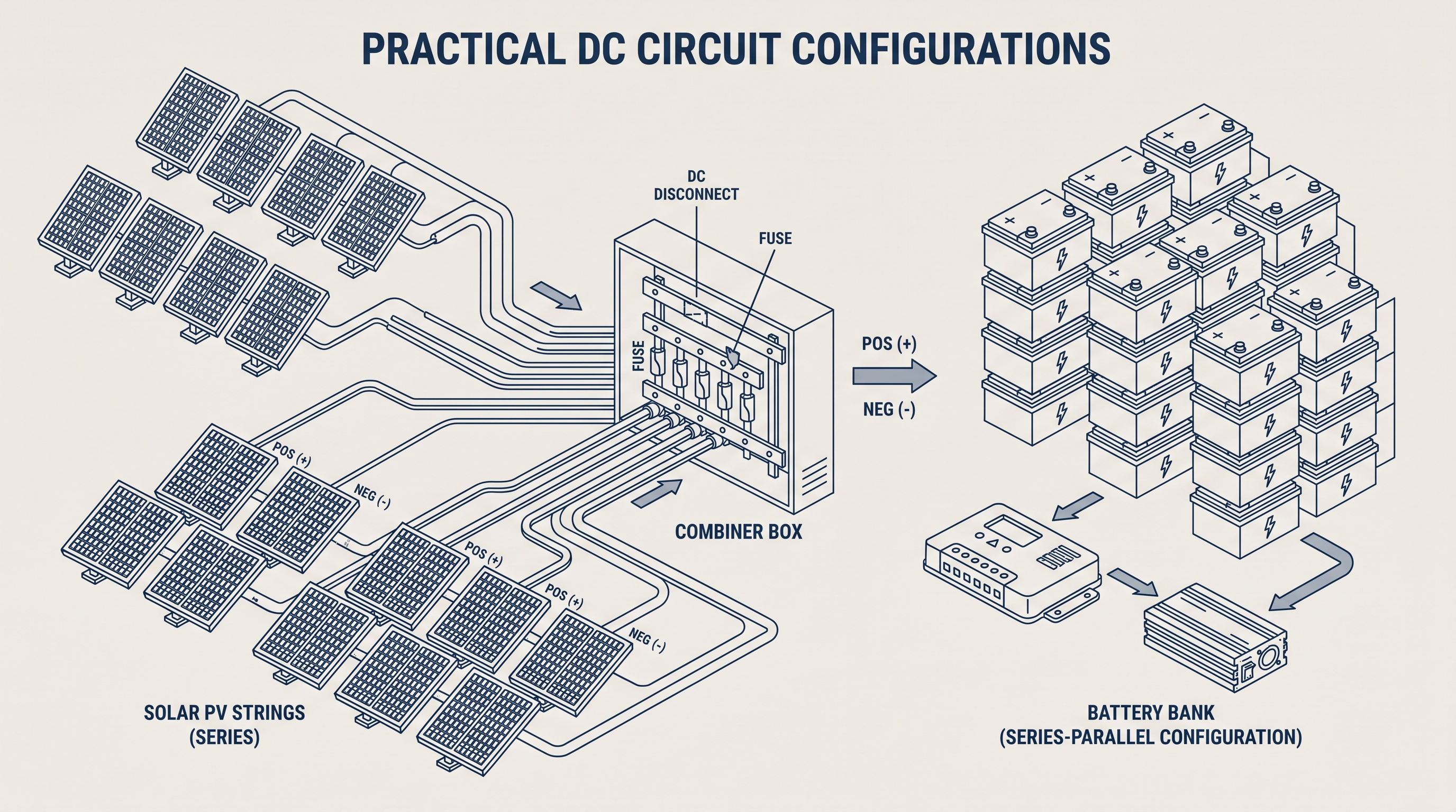
- Solar Photovoltaic (PV) Arrays: Solar cells and modules are connected in series into strings to build system voltage (e.g., 1000 V DC), and strings are wired in parallel inside combiner boxes to increase total current output.
- Battery Banks: Cells are wired in series to step up nominal voltage (e.g., 4 × 12 V batteries in series = 48 V DC bank) and parallel to increase total amp-hour (Ah) capacity.
- Sensor Voltage Scaling: Microcontroller ADC inputs (typically 0–3.3 V or 0–5 V) use resistor voltage dividers to measure higher system voltages safely.
- Building Electrical Distribution: Household appliances are connected in parallel so each device operates independently at supply voltage (120 V / 230 V).
- Current Shunts: Low-resistance precision shunts are placed in series with motor drives or inverter lines to convert high line currents into small measurable voltages.
DC Circuit Analysis Quick Reference
| Concept | Formula | Description |
|---|---|---|
| Ohm's Law | V = I × R | Relates voltage, current, and resistance |
| Series Resistance | Req = Σ Rn | Sum of all series resistances |
| Parallel Resistance | 1 / Req = Σ (1 / Rn) | Sum of inverse branch resistances |
| Two Parallel Resistors | Req = (R1 × R2) / (R1 + R2) | Product over sum shortcut |
| Voltage Divider | Vx = VS × (Rx / Req) | Finds voltage across series resistor x |
| Current Divider (2 parallel) | I1 = IT × [R2 / (R1 + R2)] | Finds current in parallel branch 1 |
| DC Electrical Power | P = V × I = I2R = V2 / R | Power dissipated by circuit element |
Summary
DC circuit analysis provides the foundation for evaluating complex electrical networks.
In series circuits, current is uniform throughout, voltage drops sum to match the source (KVL), and resistances add directly:
In parallel circuits, voltage across branches is uniform, current divides among branches (KCL), and equivalent resistance is found via the inverse sum rule:
By breaking combination networks into series and parallel blocks, applying VDR and CDR, and verifying with Kirchhoff's laws, any resistive DC network can be systematically solved.
Frequently Asked Questions
What is the primary difference between a series and parallel circuit?
In a series circuit, components are connected sequentially along a single path, meaning the exact same current flows through every component. In a parallel circuit, components share common voltage nodes, creating multiple independent current paths operating at identical branch voltages.
How do you calculate total equivalent resistance in a series circuit?
In a series circuit, total equivalent resistance is simply the sum of all individual resistances: Req = R1 + R2 + R3 + ... + RN.
How do you calculate total equivalent resistance in a parallel circuit?
In a parallel circuit, the reciprocal of total resistance equals the sum of reciprocals of each individual branch: 1/Req = 1/R1 + 1/R2 + ... + 1/RN. For two resistors, use Req = (R1 × R2) / (R1 + R2).
What is the Voltage Divider Rule?
The Voltage Divider Rule (VDR) is a formula used to calculate the voltage drop across a specific resistor in a series loop directly without determining total circuit current first: Vx = VS × (Rx / Req).
What is the Current Divider Rule?
The Current Divider Rule (CDR) calculates how entering total current splits between parallel branches. For two parallel resistors R1 and R2, branch current I1 = IT × [R2 / (R1 + R2)].
What Comes Next?
Now that you have mastered basic DC circuit reduction for series, parallel, and combination networks, the next step is exploring advanced circuit analysis techniques.
Subsequent articles cover Nodal Voltage Analysis, Mesh Current Analysis, and linear circuit theorems including Thevenin's and Norton's Theorems for solving multi-source networks.