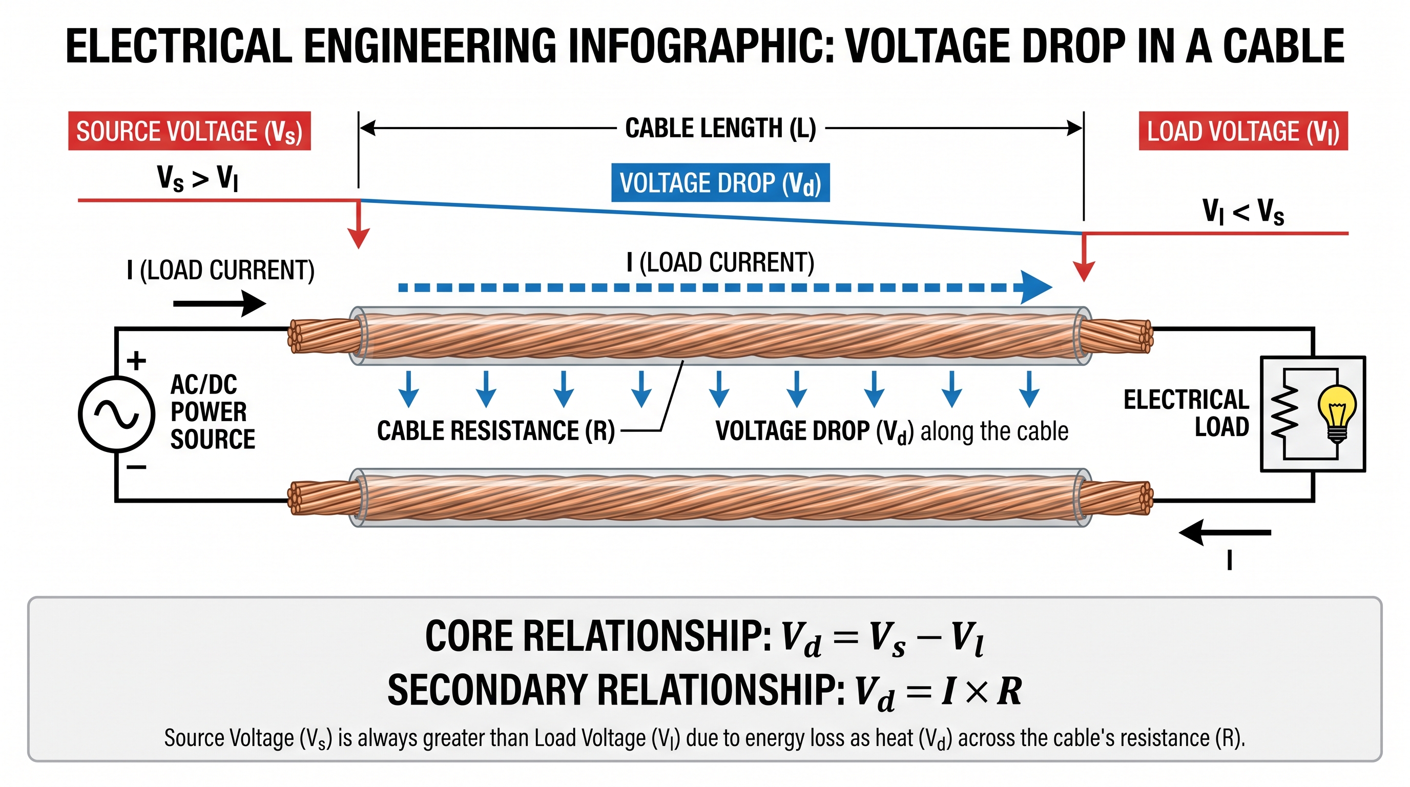
Voltage drop is the reduction in voltage that occurs as electrical current flows through a conductor, cable or other circuit component.
Every practical conductor has electrical resistance. When current flows through that resistance, a voltage difference develops across the conductor. The amount of voltage drop depends mainly on the current, conductor impedance, cable length and conductor size.
Voltage drop calculation is an important part of electrical design because excessive voltage drop can affect equipment performance, increase losses and cause unacceptable operating conditions.
What Is Voltage Drop?
Voltage drop is the difference between the voltage available at the source and the voltage available at the load after current has passed through the circuit conductors and other series impedances.
Where:
- Vd = Voltage drop
- Vs = Voltage at the source
- Vl = Voltage at the load
Why Is Voltage Drop Important?
Electrical equipment is normally designed to operate within a specified voltage range. If the voltage at the equipment terminals becomes too low, the equipment may not operate correctly.
Excessive voltage drop can contribute to:
- Reduced equipment performance
- Motor starting problems
- Reduced lighting performance
- Additional conductor losses
- Poor system voltage regulation
- Increased stress on equipment in applications sensitive to supply voltage
Voltage drop should therefore be considered together with current-carrying capacity, short-circuit requirements, installation method, equipment requirements and applicable electrical standards when selecting conductors.
Basic Voltage Drop Formula
For a simple resistive circuit, voltage drop can be calculated using Ohm's Law:
Where:
- Vd = Voltage drop in volts (V)
- I = Circuit current in amperes (A)
- R = Circuit resistance in ohms (Ω)
This equation is useful for understanding the fundamental relationship between current, conductor resistance and voltage drop.
Cable Resistance and Voltage Drop
The resistance of a conductor depends on its material, length, cross-sectional area and temperature.
Where:
- R = Resistance in ohms (Ω)
- ρ = Resistivity of the conductor material
- L = Conductor length
- A = Conductor cross-sectional area
This relationship shows why longer conductors generally have greater resistance, while larger conductor cross-sectional areas generally have lower resistance.
Single-Phase Voltage Drop Formula
For a simple single-phase two-conductor circuit, current travels through the outgoing conductor and returns through the other conductor. Therefore, when conductor resistance is expressed per unit length and the cable length is the one-way distance, the outgoing and return paths must both be included.
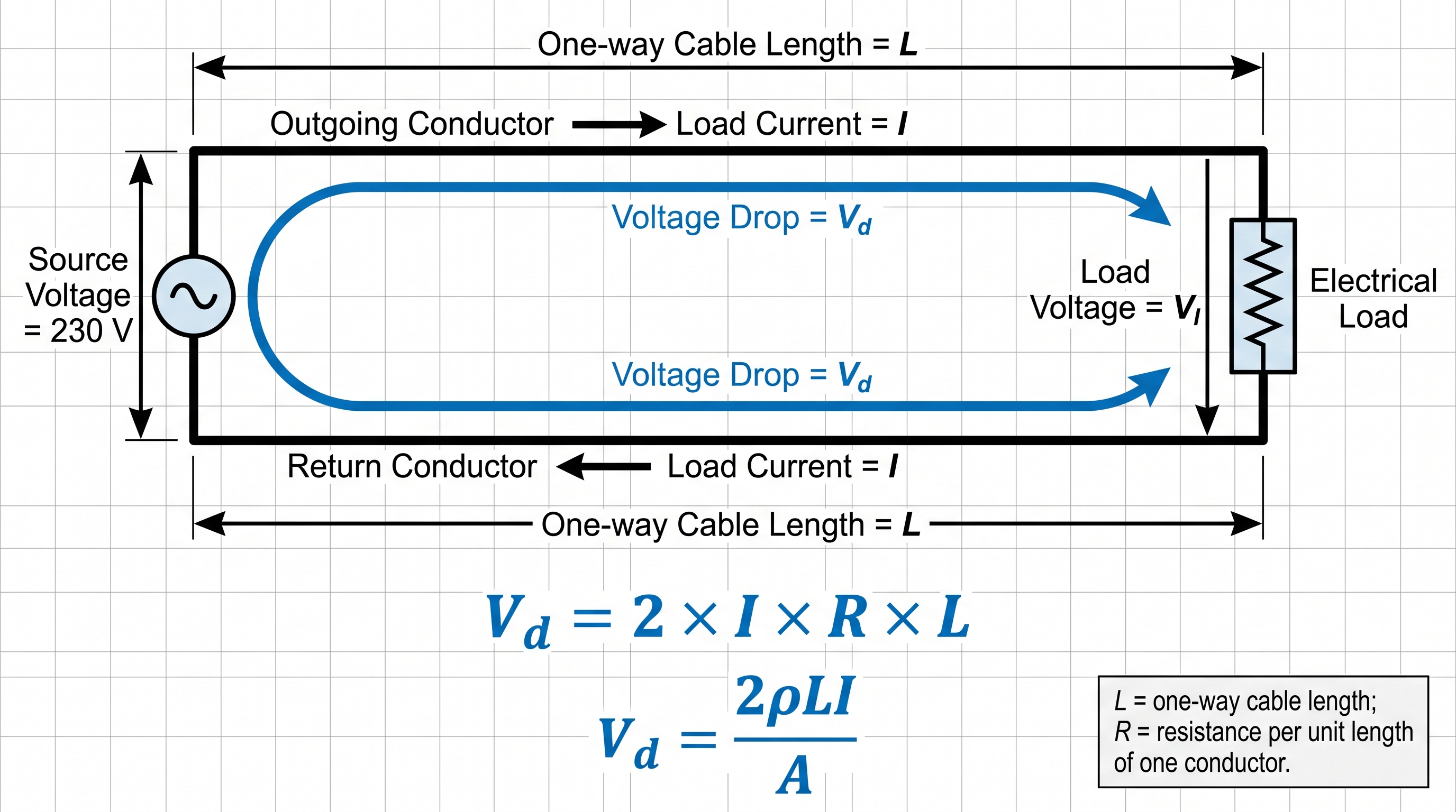
A commonly used simplified form based on conductor resistivity is:
These formulas assume a simple two-conductor circuit and do not by themselves account for inductive reactance or other installation-specific effects.
Three-Phase Voltage Drop Formula
For a balanced three-phase circuit, a commonly used simplified resistive relationship is:
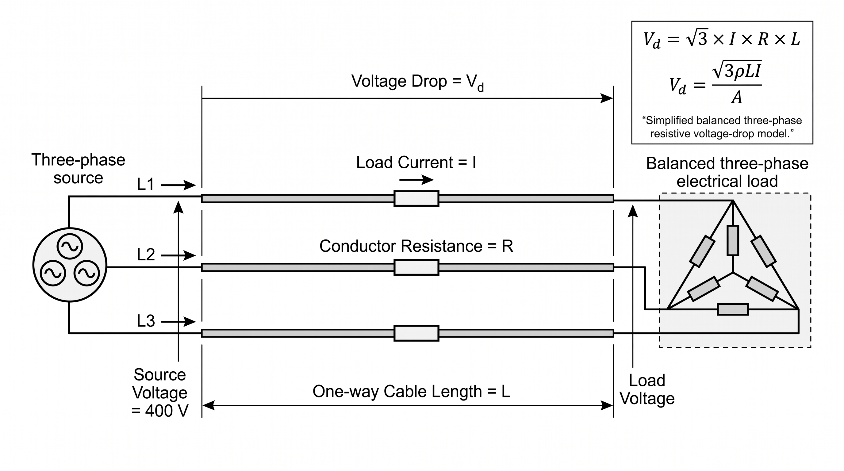
When conductor resistance is calculated from resistivity and conductor area, the relationship can be expressed as:
In practical AC systems, cable reactance and load power factor can also affect voltage drop. Detailed calculations should therefore use both resistance and reactance where appropriate.
Percentage Voltage Drop
Voltage drop is often expressed as a percentage of the nominal or reference system voltage.
For example, if a 230 V circuit has a voltage drop of 6.9 V:
Therefore, the voltage drop is 3%.
Single-Phase Voltage Drop Example
Consider a 230 V single-phase load drawing 20 A. The one-way cable length is 30 m and the cable resistance is assumed to be 0.012 Ω/m for one conductor.
Given
- Supply voltage = 230 V
- Current = 20 A
- One-way cable length = 30 m
- Conductor resistance = 0.012 Ω/m
Because the circuit has outgoing and return conductors, the total conductor length is:
The total conductor resistance is:
Therefore:
The percentage voltage drop is:
Therefore, the calculated voltage drop is 14.4 V, or approximately 6.26%.
Three-Phase Voltage Drop Example
Consider a balanced three-phase 400 V load drawing 50 A. The one-way cable length is 50 m and the conductor resistance is assumed to be 0.0005 Ω/m.
Given
- System voltage = 400 V
- Current = 50 A
- Cable length = 50 m
- Conductor resistance = 0.0005 Ω/m
Using the simplified three-phase relationship:
The percentage voltage drop is:
Therefore, the simplified resistive voltage drop is approximately 2.17 V, or 0.54%.
How to Calculate the Voltage at the Load
Once the voltage drop has been calculated, the approximate load voltage can be found by subtracting the voltage drop from the source voltage.
Using the earlier 230 V example:
Therefore, the approximate voltage available at the load is 215.6 V, based on the simplified voltage-drop calculation.
AC Voltage Drop and Power Factor
In AC circuits, voltage drop is not always caused only by conductor resistance. Cable reactance can also contribute to voltage drop, particularly in longer circuits and larger electrical systems.
For an AC circuit, the voltage-drop calculation may therefore require conductor resistance, reactance and load power factor.
A commonly used approximate relationship for a balanced three-phase circuit using line-to-line voltage is:
Where:
- I = Load current
- L = Cable length
- R = Cable resistance per unit length
- X = Cable reactance per unit length
- cosφ = Load power factor
- sinφ = Sine of the load power-factor angle
The exact calculation method and sign convention can vary depending on the circuit arrangement, conductor configuration, load characteristics and engineering standard being used.
Factors Affecting Voltage Drop
Several factors influence the voltage drop of an electrical circuit.
1. Load Current
For a resistive conductor, voltage drop increases with current:
2. Cable Length
Longer conductors generally have greater resistance. Therefore, increasing cable length generally increases voltage drop.
3. Conductor Size
Increasing the conductor cross-sectional area reduces resistance and therefore generally reduces voltage drop.
4. Conductor Material
Copper and aluminium have different electrical resistivities. The conductor material therefore affects resistance and voltage drop.
5. Temperature
Conductor resistance changes with temperature. Detailed calculations should therefore use appropriate conductor resistance values for the expected operating conditions.
6. Power Factor and Reactance
In AC circuits, the load power factor and conductor reactance affect the relationship between current and voltage drop.
How to Reduce Voltage Drop
If the calculated voltage drop is excessive, several design approaches can be considered.
- Increase the conductor cross-sectional area
- Reduce the cable length where practical
- Use a conductor material with suitable electrical conductivity
- Reduce unnecessary connection and contact resistance
- Improve power factor where appropriate
- Review the circuit configuration
- Select a suitable system voltage where permitted by the project design
Voltage Drop and Cable Sizing
Cable sizing should not be based only on ampacity. A conductor that can safely carry the design current may still produce excessive voltage drop if the circuit is long.
A practical cable-selection process should consider design current, installation conditions, conductor ampacity, voltage drop, short-circuit withstand capability and other applicable requirements.
Cable Size Comparison Example
Increasing conductor size generally reduces resistance and therefore reduces voltage drop. The following simplified comparison illustrates the effect.
Example comparison
Assume the same circuit current, cable length and conductor material are used, but the conductor cross-sectional area is increased.
- Option A: Smaller conductor with higher resistance
- Option B: Larger conductor with lower resistance
Because:
R = ρL ÷ A
increasing the conductor area A reduces resistance. With current held approximately constant, the resulting voltage drop also decreases.
| Parameter | Smaller Conductor | Larger Conductor |
|---|---|---|
| Cross-sectional area | Lower | Higher |
| Resistance | Higher | Lower |
| Voltage drop | Generally higher | Generally lower |
In an actual project, the selected cable must still satisfy ampacity, temperature correction, installation method, short-circuit withstand, protection and applicable voltage-drop requirements.
Voltage Drop Calculation Summary
| Parameter | Relationship | Effect on Voltage Drop |
|---|---|---|
| Current | Vd ∝ I | Higher current generally increases voltage drop |
| Cable length | Vd ∝ L | Longer cable generally increases voltage drop |
| Conductor area | R ∝ 1/A | Larger conductor generally reduces voltage drop |
| Resistivity | R ∝ ρ | Higher resistivity increases resistance |
| Temperature | Resistance varies with temperature | Can change the calculated voltage drop |
| Power factor | Affects AC impedance-related drop | Can affect total AC voltage drop |
Common Voltage Drop Calculation Mistakes
Several common mistakes can lead to incorrect voltage-drop calculations.
- Forgetting the return conductor in a single-phase circuit
- Using the wrong cable length
- Confusing conductor resistance with total circuit resistance
- Ignoring conductor temperature
- Using a simplified resistive formula for an AC system without considering reactance where required
- Using an inappropriate power factor
- Comparing voltage drop with an incorrect reference voltage
- Selecting cable size based only on ampacity
Practical Voltage Drop Calculation Procedure
A practical calculation can be organized into the following steps:
- Determine the system voltage.
- Determine the design load current.
- Determine the circuit configuration.
- Determine the cable length and the relevant current path.
- Obtain conductor resistance and, where required, reactance from appropriate data.
- Account for conductor temperature and installation conditions where required.
- Calculate the voltage drop.
- Calculate the percentage voltage drop.
- Calculate the expected load voltage.
- Compare the result with the applicable design requirement.
- Increase conductor size or modify the design if necessary.
Summary
Voltage drop is an important consideration in electrical circuit and cable design. It occurs because practical conductors have resistance and, in AC systems, may also have reactance.
For single-phase and three-phase systems, the appropriate circuit configuration must be considered when determining the voltage-drop path.
Voltage drop is affected by current, cable length, conductor size, conductor material, temperature, power factor and cable impedance.
The load voltage can be approximated from:
A proper electrical design should therefore check voltage drop together with ampacity, short-circuit performance, installation conditions and applicable electrical standards.